WERA is an Oceanographic HF Radar providing simultaneous measurement of:
- Surface currents maps
- Ocean waves parameters and maps
- Wind direction (wind speed under development)
These measured data are available
- Over long distances (up to 200 km) and large areas
- with good temporal resolution (complete data set within less than 10 minutes)
- with high spatial resolution (down to 300 m)
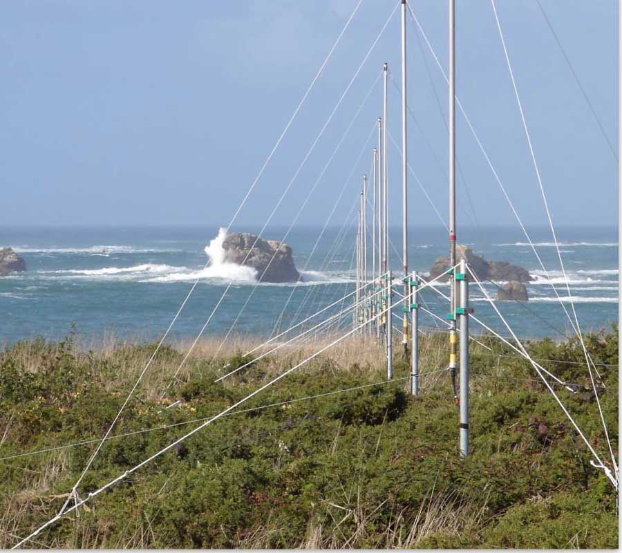
Receive antenna array on Key Biscane (left) and (right) surface current map during the passage of Tropical Storm Henry on the 5th of September 2003 east of Florida. (Data are kindly provided by Prof. Nick Shay at RSMAS)
Applications
WERA provide a lot of useful data for various applications. Typical users are:
- meteorological institutes
- coastal management (erosion, flooding, pollution, etc.)
- port authorities & harbour management
- environmental monitoring & research
- oil & gas industries
- oceanographic researchers
- vessel traffic services (ship tracking is under development)
- renewable energy providers (wind farm planning and management)
- component for tsunami warning systems
The system was developed in co-operation with Institute for Oceanography of the University of Hamburg. A first production stage system passed its field test at the Spanish west coast near Gijon in October 2000. In the meantime over 20 further systems are installed world wide.
The WERA (WavE Radar) is a shore based over the horizon radar with a range of up to 200 km, depending on the operating frequency. The system concept is broadband and modular to optimise the configuration to the users requirements. The main features are:
- Simultaneous measurement of surface currents, wind direction and wave parameters.
- Flexible receiving antenna designs (4 to 16 antennas) to be used in direction finding (4 antennas) or beam forming mode
- Frequency chirp with in continuous wave mode (FMCW), not gated or pulsed to get best signal to noise performance and to reduce interference problems
- No blind range in front of the radar
- Modular design, same components can be used for high resolution short range configurations or for long range applications.
Principles of operation
Oceanographic High Frequency Radars are simple in concept: electromagnetic waves (EM) sent to the ocean are backscattered on surface waves of exactly half the radio wavelength, just like X-rays are scattered in crystals.
Principle of Bragg scattering Incident electromagnetic (EM) wave in red and gray shading. Top: coherent superposition of reflected EM waves when the ocean wave has exactly 1/2 the EM wavelength. Bottom: incoherent superposition of reflected EM waves when the ocean wave has 0.9/2 the EM wavelength.
Since the ocean is generally covered by waves of many different wavelengths and directions (continuous spectrum), there are always trains of waves propagating toward and away from the radar. The return signal from either train will be Doppler-shifted by the wave velocity, which is known exactly by the gravity wave dispersion relationship. Thus the spectrum of the return echoes consists of two peaks, symmetric with respect to the transmit frequency, in the absence of currents.
Typical backscattered spectrum. The main spectral peaks correspond to the incident signal Doppler-shifted by the motion of the Bragg waves (after Gurgel, 1999).
If the waves ride on an ocean current, the return signal is further Doppler-shifted by the radial component of the current, which can be readily estimated. With two radars some distance apart along the coast, vector currents can be computed.
This is a precise concept, which surprisingly has taken more than three decades to be accepted by the oceanographic community (a list of early references compiled by Robert Stewart can be found here). Yet unlike Acoustic Doppler Current Profilers (ADCP), the scattering targets are well known, and well understood theoretically.
Wind direction can be inferred from the amplitude of the main peaks, and multiple scattering allows the extraction of spectral information on the wave field.
Although they have historically been called “radars”, they have nothing in common with microwave navigation radars; they in fact use very low power transmitters in the high frequency band (3 to 50 MHz), much like Citizen Band radios.
High Resolution, Long Range System Specification
- Broad frequency range from 5 to 50 MHz to provide ranges from 10 to 200 km
- Very low RF-power typically 4 x 7 W to guarantee no interference with other radio services
- FM-cw principle provides best signal to noise performance and high temporal resolution
- Robust and small antenna system
- Modular system with 4 channels for current mapping or 8 to 16 channels for wave maps, two radar
- sites required to generate 2 dimensional maps